Last articles
Transmissions info
About transmissions

Transmission general data
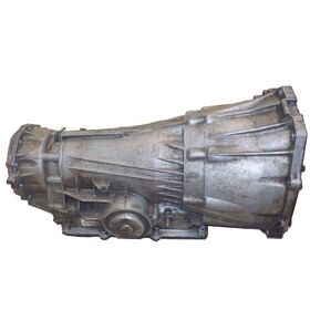
The automatic transmission 4L85E was firstly presented in 2001 together with powerful engines Duramax V8 (with torque reaching up to 650 Nm). This transmission was installed only on large SUVs, pickups and minibuses. This transmission is very powerful and can be applied cars which take part in off-road racing, drag racing or custom street driving.
Number of gearsTransmission TypeDriveTorque (Nm)ATF (full capacity) LATF (change) LATF type4ATRWD/4WD65013,6Dexron VI
These transmissions have issues with early style 12 pin harnesses in which transmission fluid leaks around the harness and shorts the pinouts causing transmission to go into "limp mode" (some manuals say "limp home mode"). This issue can be easily rectified by simply cleaning the plug
Which cars run with this gearbox?BrandModelYearTypeEngineChevrolet/GMVAN FULL SIZE 350095-094 SP RWDV6 4.3L V8 4.8L 5.7L 6.0L 7.4L 8.1L 6.5L 6.6L DIESEL
Transmission general data
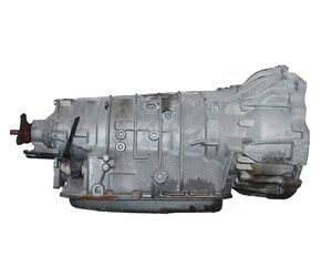
The 4-speed automatic transmission 4L40E produced by GM found application on the most common BMW 318 (since 1998). This automatic transmission was designed on the constructive basis of a reliable 4L60E, but were produced in Europe for the Bavarian automobile factory. This range of automatic transmissions replaced the 4-speed 4L30E and had been in production until 2007, when GM replaced these transmissions with the 6-speed 6L45. In terms of design the 4L40E (5L40) is the most simple, robust and reasonably priced transmission.
Number of gearsTransmission TypeDriveTorque (Nm)ATF (full capacity) LATF (change) LATF type4ATRWD36095,5-6Dexron VI
Technical issues and repair guidelines
The repair of this transmission mainly lies in the replacement of filter, gaskets and seals (preventing oil leakage), and replacement of burnt friction elements. All parts are interchangeable with 5L40E and 5L50E. Frictions are one-sided as in the popular DP0 transmission. The pack (Direct Clutch; 2nd Coast) burns twice as frequently as other clutch packs.Generally, this gearbox is considered to be reliable and almost “invincible”, when avoiding heavy ATF contamination by friction dust and the abradant which wears out not only friction nodes, but also the valve body.
This issue (oil contamination) often results in self-regulating pump becoming “unregulated”, also remaining in the mode of ultimate capacity. It leads to the rapid gear-shifting as well as to increased pressure in packages resulting in pistons damage. Issues with pistons is a typical soft spot for the 5-speed 5L40E and 5L50E (BMW Х5). The rubber-covered piston (forward) most commonly gets out of order because of its design peculiarities.It is usually recommended to take care about the ATF quality for this transmission.
Which cars run with this gearbox?BrandModelYearTypeEngineBMW3-SERIES00-054 SP RWDL4 1.9L L6 2.0L 2.8L
How to repair this transmission (Videos)Part 1 Transmission ServicePart 2 Transmission Service
Instruction manuals and useful linksLink typeSourceDescriptionpdfshinseiauto.comScheme 4L40E
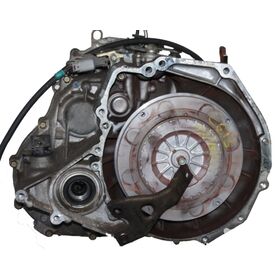
Transmission general data
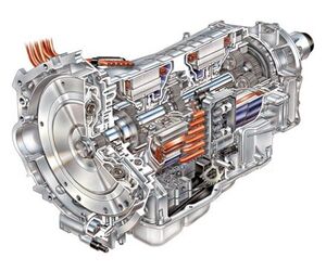
The
2ML70 gearbox is a 4-speed rear drive which can be configured in a two or four
wheel drive application. The secret of this transmission lies in combination of
2 electric motors inside the transmission, which serve not only for driving the
car under certain conditions, but also for starting the engine. The 2ML70
transmission has several important advantages when compared to its gasoline
counterparts: reduced fuel consumption, improved performance characteristics,
reduced amount of toxic emissions.
Number of gearsTransmission TypeDriveTorque (Nm)ATF (full capacity) LATF (change) LATF type4Hybrid SystemRWD51512.310.8Dexron VI
This
transmission doesn’t have a torque converter. It is equipped with stop/start
technology and therefore has a 12 volt auxiliary pump to keep the 1-2 clutch
primed any time the engine shuts down. The design of 2ML70 also includes 3
planetary gear sets, 2 rotating clutch packs and 2 fixed clutch packs. The
gearbox functioning is controlled by a Transmission Control Module (TCM) which
is located inside the transmission and the hybrid systems operation is
controlled by the Hybrid Control Processor (HCP) located under the hood.
Which cars run with this gearbox?BrandModelYearTypeEngineBMWX609-14EVT 4WDV8 4.4LCadillacESCALADE HYBRID07-13EVT R/4WDV8 6.0LChevrolet/GMSILVERADO HYBRID/SIERRA HYBRID09-13CVT R/4WDV8 6.0LChevrolet/GMTAHOE HYBRID07-13CVT R/4WDV8 6.0LChevrolet/GMYUKON HYBRID08-13EVT R/4WDV8 6.0LChryslerASPEN HYBRID9CVT R/4WDV8 5.7L HEMIDodgeDURANGO HYBRID9EVT R/4WDV8 5.7L HEMIMercedes-BenzR CLASS09-11CVT R/4WDV6 3.5L
How to repair this transmission (Videos)GM Two Mode HybridWhat is a two-mode hybrid?
Instruction manuals and useful linksLink typeSourceDescriptionwebwww.searchautoparts.comAN INTRODUCTION TO GM'S 2ML70 TWO MODE HYBRID TRANSMISSIONpdfwww.atraonline.com2ML70 (RPO M99)
Transmission general data
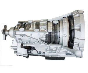
The 10R80 is a 10-speed automatic gearbox
designed thanks to fruitful cooperation between Ford and GM (10L90). Both companies
pointed out the fact that while the mechanical part of the gearbox was
developed collaboratively, the software part of the 10R80 will be different for
each manufacturer and, as a result, their corresponding powertrain structures
should not necessarily resemble each other in view of gear shifting algorithms.
This transmission has 10 forward gears, three of which are overdrive ratios.
It's deep 4.69 to 1 first gear ratio is the lowest in its class and it features
a relatively tall 0.63 to 1 final overdrive ratio.
Number of gearsTransmission TypeDriveTorque (Nm)ATF (full capacity) LATF (change) LATF type10ATRWD/4WD80012.98Motorcraft ULV
A built-in electrohydraulic pump ensures that
the "start-stop" feature operates with minimal delay. The 10R80 includes
3 operation modes - "Tow Haul", "Sport", and
"Normal", with each mode changing the gear shifting algorithm and
characteristics to compliment particular forms of driving behavior. Since the
gearbox has 10 forward gears, its running characteristics and, more
importantly, fuel efficiency is maximized by the transmission's capacity to get
a suitable ratio for current operating conditions, such as engine speed, load,
and car speed. This transmission became a standard option for the 2017 F-150
equipped with the 3.5L Eco-Boost engine.
Which cars run with this gearbox?BrandModelYearTypeEngineFordF-1501610 SP R/4WDV6 3.5L V8 5.0LFordF-150 SUPERCREW1610 SP R/4WDV8 5.0LFordMUSTANG1610 SP RWDL4 2.3L V8 5.0L
How to repair this transmission (Videos)10-speed Transmission Assembly
Instruction manuals and useful linksLink typeSourceDescriptionwebwww.f150hub.com0R80 10 SPEED AUTOMATIC TRANSMISSION RATIOS
Transmission general data
3-speed automatic transmission 3HP22 was
produced by ZF company in 1973. This transmission was intended for rear drive passenger vehicles with motors M10, M20,
M30
of BMW product range (big coupes and sedans, 3, 5, 6 and 7 series). This automatic transmission
transmits the torque up to 320 Nm.
Number of gearsTransmission TypeDriveTorque (Nm)ATF (full capacity) LATF (change) LATF type3ATRWD3202.42Dexron II
Technical issues and repair guidelines
One of the most common sources of problems in this 3HP22 transmission is the governor. The governor is a shifting pressure regulator on the output shaft of the transmission. The gear shifting point according to the car speed depends on the above mentioned governor.The wear-out of niches for plastic rings on the hub of the last transmission clutch is considered to be another soft spot. This problem also may lead to the governor pressure loss.
How to repair this transmission (Videos)3HP22 valve body rebuild
Instruction manuals and useful linksLink typeSourceDescriptionwebwikipediaZF 3HP22 transmission
Transmission general data
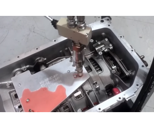
Leak test units allow checking circuit integrity for transmission units through use of hydraulic pressure. These tools guarantee time saving since modern models do not require removal of the transmissions off vehicles. It is a universal machine which merely requires appropriate leak test plate to fit any automatic gearbox. The 4L60 transmission, 4L80 transmission, ZF transmissions are some of the most demanded for this transmission service.
The answer to the question on the reason of oil flowing out of the transmission troubles many transmission specialists. Transmissions oil leakage is in the group of problems with which almost every driver ever found. Under the car there are oil stains that are gradually increased. Set of lubricants is considered to be an important part of the vehicle. Such a problem leads to major failures. Friction of the contacting parts goes uncontrolled, wear debris is stopped from leaving the drivetrain, the assembly doesn’t cool down. It is unsafe and could cause fire.
Various leaks at the junction of gearbox and engine most likely can occur due to the following reasons: wear-out or failure of seals, various defects in shafts and seals, emergence and increase of clearance in the shafts (input shaft, etc.), sealing compound fails to provide the desired sealing, loosening of clamp holdings, failure of properties of seals and gaskets and other effects.
Transmission general data
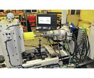
Dyno stands allow testing complete gearboxes in assembly checking their performance and understand if it is comparable to benchmark characteristics. It is the tool that is certainly needed to provide certified transmission quality. There are options that allow advanced testing of FWD, RWD, AWD automatic transmission vehicles, for both civil and heavy duty models. A dyno stand used to be an expensive option for big-scale car transmission rebuilders but more accessible quality options start to emerge on the international transmission service market.
Why is it important to use a transmission dyno test stand?
What are key components of a transmission dyno?
What is the difference between electric motor and combustion engine dynos?
Principle of operation |
What types of load cells are there in the dynos?
History of transmission dynos on the industry market
Pressure gauges in transmission dynos
Importance of hardware with transmission dyno stands
Importance of software with transmission dyno stands
Major suppliers of automatic transmission dynos
The
transmission of an essential part of a vehicle drivetrain system, transferring
power to the wheels, doing gear switching, distributing load. Depending on the
context, to a large degree term ‘transmission’ is synonymous to ‘gearbox’.
What is the utility of using transmission dyno test equipment?
In the
transmission repair industry, testing of a complete automatic transmission unit
is imperative for large remanufacturing companies dealing with large repair volumes,
is quite desirable for medium-scale companies working widely on the national
level and supplying to other countries, and is a dream for smaller transmission
shops that always do test-on-the-car checks to verify the repair procedure. In
addition, many educational institutions (like tech colleges) need dynos for
proper students’ skill-learning process. Production companies use transmission
dynos in their EOL tests (end-of-line testing).
“Dynamometer”
consists of two words - dynamo (Greek for “power in motion”) and meter (also
Greek for “measurement”). Very often, it is simply called as “dyno”. A dyno
stand used to be a costly tool solely for big-scale transmission rebuild shops,
nowadays, however, more accessible options of these tools are emerging on the
international transmission service market.
One who is new to transmission repairs may actually
wonder: ‘Why a transmission should be dyno tested?’ It is primarily about
warranties and guarantees given by the provider of repair services. A dyno test
ensures that a transmission is performing well and adequately under certain
conditions of operation and this gives a huge grade of certainty that the
transmission will last full life expectancy.
The dyno testing means that you mount a transmission
in the dyno test rig and drive it through various paces. The idea of such
testing is simulation of real-life operation conditions as if it were driven in
the car on the road. At this, the gearbox is taken through a complete set of
operations, with gear and speed switching, and in each gear operation is
performed through the design speed range. Certainly, it is vital to capture
output values, and these are monitored in the test process.
Reputable transmission remanufacturers set their goal
to return the rebuilt product to original factory specifications. With dyno
testing, the following key parameters are checked: torque, temperature,
pressure. Also, operations efficiency is checked and sensor functionality test
is performed. The tech operator is able to verify bolt torque and presence or
absence of leaks in the system. To put it straight, the dyno test assures that
your gearbox operates according to the factory specifications with due regard
to design speed and range of gears.
You need to dyno test gearboxes when:You strive to provide top quality
of your rebuilds.
You want to be sure of the
longevity of warranties that you give.
You want to speed up your repair
processes.
Your partners who contract you in
large volumes need assurance of compliance with highest reman standards.
You value your shop’s reputation
and you want to avoid unwanted returns damaging
Basically, without dyno testing you have difficulty
proving that the gearbox will not fail in operation conditions. Although the
guarantee might have a fault covered, it is your reputation that you need to
protect and avoid frustration when a gearbox is returned back with faults.
What is more, health of the transmission means that no
harm will be done to the drivetrain and no further damage to the engine.
Another vital idea is that a high quality reman transmission can be better
performing than a new factory one. This is important for transmission
performance shops and racing car
workshops.
What are key components of a transmission dyno?
It is important to understand key components of a dyno
test rig as a transmission specialist may wonder how it functions.
Primarily, modern
dynos are fully digital and allow for highly accurate easy-to-perform
repeatable automotive transmission testing. The important factor here is
software and hardware, which is realized in the controller system. These dynos
simulating automotive load conditions are typically quite universal and
adaptable to various modes of wheel drive and automatic transmission types
(including CVT transmissions). In order to cover this universality the test rig
is performed with due regard to capacity requirements, motor horsepower specs,
number of load cells. Let us cover the components of the body of a transmission
dyno.
High-output motor (nowadays it
would be an electric motor)
Load unit (for dynamic loaded
testing). At this, number of load cells is varied for various applications: 1
unit – for RWD (rear-wheel drive) vehicles, 2 units – for FWD (forward-wheel
drive) vehicles, 3 units – for AWD (all-wheel drive) vehicles
Jib crane for transmission mounting
and dismounting
Pumps with hoses to fill and drain
transmission fluid
Pressure sensors
Oil tank and drip trays
Stall brake
Quick release hose fittings
Additionally:
Electric shuttle motors allowing
positioning for different transmission configurations
Tooling kits for transmission
positioning avoiding any potential harm to pumps or certain transmission
components
Bushings for precise transmission
alignment
What is the difference between electric motor and combustion engine dynos?
Modern dynos run on electric motors, they use
electricity stored in batteries and power electromagnets driving axles.
Combustion engines run on gasoline, which
explodes in an enclosed space – it is a well-known process happening in most of
the cars driving on our roads, hence the name. In vehicles, this combustion
moves pistons, which rotate engine’s crankshaft and all that controls rotation
of the vehicle’s axle. This solution is pretty much obsolete and not used in
up-to-date dynos for a number of reasons:
CE has many more parts and occupies
more space (CE with ~2000 parts and EM with ~20 parts). Fewer parts also means
easier serviceability and maintenance.
Disposable fuel with electric
motors, while in a combustion engine, the disposable fuel is gasoline, which
must be carefully stored, as there is a danger of ignition. What is more, fuel
leftovers must be exhausted out of the after combustion.
Electric motor battery packs are
expensive but gradually become more accessible.
With electric motors little energy
is wasted, but with combustion engines quite a serious percentage of energy is
lost along the way. Therefore, it’s the gas-powered vehicle that needs more
energy.
It is more comfortable and
convenient to service an electric motor in a transmission shop surrounding, if
comparing to a combustion engine.
Overall, 75kw (or ~100 horse power) is enough to
drive modern transmission dynos for light-duty and medium-duty application. At
that, electric motors are very much preferred.
Principle of operation
It is
important to distinguish transmission test stands from these two types of dyno
stands: engine dynamometers and chassis dynamometers. With engine dynos, the
engine is removed from the vehicle and installed on the stand by connecting
directly to the flywheel. For this purpose, transmission specialists use
special adapters and it is also necessary to connect the cooling system, as
well as some other components - this procedure takes a lot of time. Engine
developers and manufacturers mainly use these stands.
Chassis dynos allow for testing of the vehicle
as it is driving on the road, fully assembled. These are rather popular among
people doing racing cars or performance vehicles.
Transmission
testing stands are suitable for both transmission manufacturers and
transmission repair service shops. During testing of complete gearboxes their
performance is compared against benchmark characteristics. Multiple readings
are taken using corresponding sensors and transducers, their readings are
converted to visually explicit and perceivable information. Obviously,
transmission dynos vary in their design to cover FWD, RWD, AWD automatic
transmission vehicles, support and fit civil light-duty and/or heavy-duty
models. Precision alignment tooling and data acquisition & control systems
play an important part in quality transmission testing.
What types of load cells are there in the dynos?
Dynamometers are classified by the method of creating
a load. Nowadays, the accepted brake standard in a transmission dyno is eddy
current brakes.
EC brake is an electrically controlled brake with air
cooling. In it, load is created by inducing a magnetic field in a rotating
disc. Heat produced by the rotating disc is dissipated in air. Moving parts are
stopped by EC brakes with the help of drag force. These brakes are a great
option for lower power applications and dynos up to 250 hp.
Water brake works on the transfer of water momentum
creating load on the tested unit with the absorbed power heating water.
Usually, these consist of a turbine / propeller, which is mounted in an
enclosure with water. Water brake are for high power applications far over 250
hp. Largely, for engine dynos with thousands of hp.
Alternating current dynamometers are another option
which is less frequent when compared against EC’s. These are used for engine
dynos and the idea is in mimicking the load placed on the engine as it powers
vehicle.
History of such equipment on the industry market
Transmission
testing equipment has a particular history in the USA, the leader of car
industry. The world’s largest manufacturer for this type of equipment –
PowerTest – is located in Wisconsin. They started in 1976 and grew to acquire a
large number of brands and companies from the industry. Nowadays, PowerTest
owns such brands as AIDCO, Axiline, Hicklin – all of them shall be known to
people who spent decades in the transmission industry.
Another
well-known US manufacturer is MAE (Mustang Advanced Engineering) who were on
the market since 1970’s as well. As of today, they provide a system for testing
automatic passenger car and light truck inline and transverse transmissions as
well as systems for medium- and heavy-duty applications.
There are
some other companies located in the USA but they are far less active and less
known to a global audience, as of today.
Although, dynamometers have been around since as
far as the 18
th century, quality transmission dyno options are not
as many as one might have thought.
In the 21st
century, USA are not sole prominent manufacturers and they need to compete with
companies like RayTech from China or Hydra-Test from the UK for the global
buying audience.
Pressure gauges in transmission dynos
In previous decades, the equipment output gauges were
analog but nowadays there is obvious tendency for digitalization. With modern
control systems, the process of running through gears and checking electronic
solenoids is automated. One single system runs many different vehicle and
transmission types.
If a transmission stops working because of a sensor,
harness, connector or solenoid, it will be visually shown on the screen,
explicitly as to identify this failure. Comprehensive data on each sensor can
be compared against the benchmark result and thus it will be easy to determine
whether that particular sensor is good or bad.
Multiple fluid
pressure gauges enable thorough shift timing evaluation and adjustment.
Controller box ordinarily comes for 8 pressure sensors with quick fit
connectors. This can be expanded to 2x times (total 16 pressure sensors) if
this happens to be required in the technological process. Readout in modern
dynos is easy to adjust for any needs – especially if the software is
appropriate for client-specific demands.
Importance of hardware with transmission dyno stands
Modern
advanced dyno stands allow control and full testing of electronically shifted
Mechatronic gearboxes and valve bodies. The importance of hardware for such
dynos cannot be understated.
Modern dyno
stands provide complete computerized control and with that extremely precise
test procedures are easy to repeat. Some companies like Axiline concentrate on
the US domestic market. However, the range of supported gearboxes is typically
large: the dynos fit most USA home and non-national RWD, FWD, transverse, and
Continuously-Variable Transmission gearboxes. These dyno stands check:
gearbox
line pressure,
TC
lockup and downshift,
shift
point and response,
stall
speed, and more.
At this,
emulated load conditions for vehicles are applied and speed and load are
measured with potentiometers. Transmission rebuilders will be able to
confidently spot ATF and pressure leakages, check controls of the systems and
hydraulics, and perform minor corrections with the gearbox still being mounted
on the tester.
Reliability
of hardware and flexibility of software are equally important for efficient use
of transmission dynos.
Hardware is
the brain of a transmission test stand. You do not have to be an IT-specialist
to know to value enduring components that will serve to last for years and that
will be protected from any electric malfunction.
In many
cases, a physical body of the transmission dyno is still able to last for
years, however, the hardware or the controller itself is very obsolete and
cannot meet demands of those new development that have come by recently. When
looking for such an advanced tool, it is also vital to look into this aspect of
the equipment – how is it going to be supported after a couple of years of
operation.
For
instance, the most-professionally done Chinese dynos are looking really good,
but the hardware part here is just a contribution and doesn’t bear any
advantages. Axiline (at PowerTest) has quit updates for their controller system
and just go with what had been on for many years now.
A good
option to look into are companies that supply controller systems separately
form the dyno testers. This means that they are concerned about all the aspects
of the equipment: physical, hardware, software – and can deliver a lasting
product. Hydra-Test’s HTC-S is adaptable for existing dynos from former years. If
the machine has served years and is still functioning well, it can be easily
refitted with a new controller box – enhancing the functions and data
validation and processing.
For instance, among
transmission dyno users from the USA and Europe there is often a situation when
their current system is obsolete and shows the following deficiencies:
Difficult process of programming new units.
Inability to smoothly ramps solenoid current.
No support for newer developments that came into market after 2020.
Absence of reliable tech support from the manufacturer.
Current transmission controller being no longer in production.
A new
controller generation tackles these issues quite successfully and relatively
easy. If you happen to be negotiating with a particular company’s manager, ask
all of those questions upfront. New controller systems ideally have to come in
a modular format when it is possible to build up a controller from several
modules facilitating the support and any future upgrades.
New units
coming to the market can be controlled efficiently with adaptability and
flexibility of software. Ask your supplier if it is possible to write your own
test scripts, this feature may be hidden but is pivotal for efficient use of
transmission dynos.
Interpolation
feature allows for solenoid ramp up, and with ease. New developments like
Mercedes 722.6 or latest Chrysler models (like 68RFE) are supported equally
with older designs.
Technical
support is pivotal here. You do not want to be stuck with a fault that your
supplier cannot be resolved for you. Large transmission equipment companies or
companies coming from non-European countries oftentimes have these issues.
As an
important note, remember that mechatronics have a different testing method and
a 3
rd party supplier of equipment cannot have OEM access codes.
Their use is restricted and protected. Therefore, do not expect that your
transmissions can be tested along with their mechatronics components. It is
simply not the case.
Mechatronics
are excluded from the testing circuit with universal transmission dynos. They
are tested separately by individual OEM tools – like ZF Testman and the like
for other OEM’s. Double- or triple-check it if your potential supplier promises
to supply mechatronics testing with their equipment.
Importance of software with transmission dyno stands
The IT field is on the rise and its advancements have
also concerned the pretty much conservative transmission repair industry. When
considering a transmission dyno, check for the following factors:
Date of software release
Frequency of software updates
Ease of update installations
Presence of online tech support
Possibility of desk sharing
sessions (for example, via TeamViewer)
Flexibility of operational
algorithms and their adjustments to clients’ needs
Convenience of output data readout
and printing out
Attractive and user-friendly design
In fact, the software factor oftentimes goes without
notice but it plays an essential role in efficacy of the dyno system. Just
imagine running your high tech tool on Windows XP when it is 2020’s. This
discriminates the whole investment.
Major suppliers
Nowadays, it
is easy to commerce internationally and the suppliers are not limited to their
local markets. US companies supply to Europe and to Turkey, Chinese suppliers
have clients in the Middle and Near East. European suppliers have clients all
across the globe – from Mexico to New Zealand. A certain group of suppliers
works chiefly for the post-USSR countries.
1. Power Test
Active
since: 1970s
Location:
Wisconsin, USA
Types of
equipment supplied: transmission dyno test stands, engine dynos, chassis dynos,
valve body test stands, torque converter repair equipment, and other (all via
different brands – Axiline, AIDCO, TCRS)
About: on
the market for over 40 years, Power-Test has been providing test equipment to both
manufacturers and rebuilding facilities and distributors in various field of
industry. These include mining, oil & gas, power generation, and
particularly military applications, marine, and construction.
Product
updates: not recently.
Power Test
has been acquiring local USA companies under one hood and is the largest
company producing these types of products in the world. At that, the most
powerful products are by AIDCO as they are for military applications. Test
stands for transmission shops come as contributing to overall Power-Test
profile.
CHECK OUT
PRODUCTS
https://go4trans.com/superflow-dynamometers-and-fl...
2. RayTech (Guangzhou Ray Technology Solutions)
Active
since: 2010s
Location: Guangzhou,
China
Types of
equipment supplied: transmission dyno test stands, valve body test stands,
torque converter repair equipment, and transmission parts.
About: Some
Chinese suppliers cannot be counted on, simply because of how they present
their product. RayTech is different in these terms although their web presence
is also a little unclear to a European or American potential buyer. They also
take part in certain expos across the globe.
Product updates: new test plates for RayTech
equipment.
Raytech is
probably a most recognizable supplier of transmission equipment (along with a
Chinese company TranSpeed). Despite having a good portfolio and attempts to
position their products, some proper online presence could be improved. This
supplier may be best to be contacted via Chinese local trading platform.
3. HYDRA-TEST
(Cottingham Engineering LTD)
Active
since: 1990s
Location: Kettering,
United Kingdom (head office) / Minsk, Belarus (daughter production company)
Types of
equipment supplied: transmission dyno test stands, valve body test stands, torque
converter repair equipment, valve body repair tools.
About: at
this day, Hydra-Test is the only prominent and reliable transmission repair
equipment supplier from the United Kingdom. In 2019, the company opened a
subsidiary production office to be more competitive in terms of product
production cost and be able to deliver most reliable support quality. Valve
Body testers by Hydra-Test are known for durability and full coverage of
clients’ demands. Hydra-Torque equipment fabricated in the Belarusian division
since 2017 has been supplied to various countries, including a heavy-duty
application. The team is also open for custom-built solutions and delivers them
in exact match to clients’ needs.
Product
updates: Hydra-Dyno (launch of transmission dyno production), HTC-S (newest
controller generation), 0AM valve body test tool.
ThisUK
supplier is well-known for their attitude, constant update of available
solutions. Opening a production site in Belarus is also an advancement. Some companies
from post-Soviet territories can be barely counted on. However, if guided by
European service standard, it is a great combination of affordable price and
highest quality of transmission repair.
CHECK OUT PRODUCTS https://go4trans.com/hydra-torque-transmission-dyn...
4. Mustang AE
Active
since: 1970s
Location: Ohio,
USA
Types of equipment
supplied: dyno test stands for a huge variety of applications (including
transmission dynos), solenoid testers.
About: on
the market for over 40 years this company has launched a series of equipment
for various applications, including military sector, heavy-duty equipment, and
more. The company aspires to deliver creative thinking to drive continued
success. They are one of the leaders in delivering sophisticated dynamometer
technologies and advanced engineering capabilities.
Product updates: not recently.
Mustang
AE’s growth has been hindered recently but it is a supplier worth referring to
at least for comparison. A company with such a serious portfolio that includes
emission measurement system fabrication, own design services bureau and more is
certain to work on transmission repair clients’ requirements in a diligent way.
5. Extra:
We tried to contact alternative Chinese and USA suppliers to provide more info for consideration here but were treated with silence or an awkward invitation to come to China to see the machine and learn about pricing.
How to repair this transmission (Videos)RockAuto Auto Parts transmissio being dyno testedG-TEC: transmission dynoPowerglide On The DynoTransmission dyno upgrade with Hydra-Test HTC-S controllerTransmission dyno at Certified TransmissionsG-TEC: DYNO Transmission Tester for "light" vehiclesHow your Transmission was Dyno TestedSupeflow. Axiline transmission dynamomenter
Instruction manuals and useful linksLink typeSourceDescriptionpdfhttp://promand.com.auAXILINE 66K TRANSMISSION DYNAMOMETERpdfSuperflowAxiline 97000 dyno brochurepdfPowertestPowertest transmission dynos. Product brochurewebMAEMustang MAE transmission dynoswebGearstarWas your traansmission dyno tested
Transmission general data
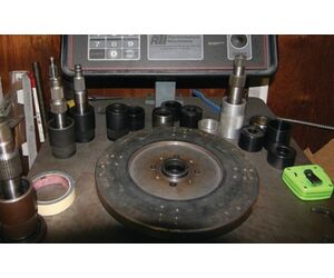
Balancing is used after all components have been replaced and subsequent welding is done. The process of balancing allows transmission service people to find out if there is a bad or uneven weld on the circumference of a Torque Converter. If it is identified, the operator can easily weld on a small amount of material or remove it. Performance transmission and racing transmission specialists pay special attention to Torque Converter balancing.
When you turn the ignition key the Torque Converter starts to rotate together with the engine. Torque Converter of about 250mm in diameter and of about 10 kg in weight imbalance in its RPM can cause such a serious vibration that the entire vehicle will be affected, including fastening elements of the engine and the automatic transmission.
Balancing machine for torque converters allows us to check imbalance of this element with guaranteed accuracy. Precision system implemented in these machines allow transmission repair experts to pinpoint exact place of excessive or insufficient weight.
Transmission general data
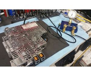
The Vacuum Test Unit is used to test the vacuum integrity of all Valve Body hoses and valves. This method of Valve Body testing is considered to be quite a traditional testing solution for transmission shops - it is a money-saver which does a straightforward job. At the same time it doesn’t provide the many advantages of the modern sophisticated transmission service tools. Vacuum tester is often used jointly with a Valve Body test equipment for remarkable results.
The vacuum test allows to evaluate the condition and wear of the valve (plunger) in the body of the hydraulic unit. A worn valve or a hole in the hydraulic unit may result in improper operation, reduced performance or malfunction of the automatic transmission. In most cases, it is possible to assess the wear of the hydraulic unit of the automatic transmission without the vacuum test. However, if you have repaired hydraulic unit with the help of special reamers and valves produced by such manufacturers as Sonnax, a vacuum tester is a must because the vacuum test allows you to quickly and easily test for leaks in the channels of the hydraulic unit.
Transmission general data
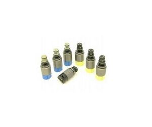
Many Valve Body problems are due to solenoid issues. Typically, a Solenoid tester is similar to a Valve Body testing unit - it is offered by the same manufacturing companies with similar software and hardware changed to do job only on Solenoids. It comes as an efficient solution to smaller-scale transmission repair businesses looking for a more affordable solution to improve their Valve Body rebuilding quality and general automatic transmission rebuild standards as well.
Solenoid testing machines are used for checking the state of solenoids produced by different manufacturers of automatic transmissions. Separate solenoid test blocks make it possible to run tests for the majority of most popular makes on the actual international market. Modern Solenoid Test machines now typically come as a universal model and allow to cover any transmission specialists’ preferences in transmission rebuilding operations.
Modern Solenoid Test tools allow possibility to run tests at maximally high required temperature and solenoids are tested as they function with the valve body, as originally designed. The automatic transmission solenoid is an electromechanical regulator in the gearbox, in response to the computer impulse it opens or closes the channel in the hydraulic unit to control flows of hydraulic fluid. Solenoids control the hydraulic switching of operation modes in modern automatic transmissions, CVT and DSG. The solenoid is inserted in the channel of the hydraulic unit and is fixed by bolts (or a pressure plate) and at the other end through the plug of the wiring harness it is connected to the electronic control unit of the automatic transmission.
How to repair this transmission (Videos)RayTech Tester for Transmission SolenoidHydra-Test Solenoid test machine guideTransmission Solenoid Testing (Ohms Law)Automatic Transmission Basic Solenoid TestingHow to test automatic transmission solenoid status: OK or Bad ?Hydra-Test HT-SOL 25 - IntroHow to test a Transmission Solenoid
Instruction manuals and useful linksLink typeSourceDescription0Gears MagazineTransmission Solenoid Test Methods0Gears MagazineUnderstanding GM 6T40 Solenoids0Gears MagazineSubaru Lineartronic CVT Lock-Up Solenoids0Gears MagazineFord Solenoid Strategy Numbers: Is It Necessary to Program?
Transmission general data
In the automatic transmission, the valve body serves as the hydraulic control center responsible for gear shifting and torque converter clutch application. Inside a valve body, one will see a maze of channels, different sets of valves, and a variety of solenoids. These all work together controlled by the transmission control unit or module (TCU or TCM) to direct hydraulic fluid through these passages to the valves activating the required clutch pack or servo to apply or release these elements causing gear changes and torque converter clutch application. Modulation of the components is what provides smooth gear changes over the range of throttle application or driving conditions.
Why is valve body testing important and necessary?
Valve body
testing covers a significant range of tasks. Among these, one may distinguish 5
principal ones as below:
Speed up the process of repair of a worn valve body,Be able to pin-point a source of malfunction within a valve body,Provide confidence in valve body repair for extended warranties,Be compliant with stringent quality requirements,Provide end-of-line testing for a new valve body as a factory product and performance valve body testing.
The only other viable option to test a valve body is to test-in the vehicle, which involves a large amount of labor and technician time especially on newer vehicles where installation and removal of the valve body may require other vehicle components to be removed to gain clearance. Simple remove and reinstallation of a valve body inside a car can take up to 4 hours to complete. If a shop is specializing in transmissions and valve bodies and repair volume is low, this might be an option that works for them, but most shops are competing on price and so the required technician time make s this an expensive option. The real issue with this method is when there is a fault or malfunction that is not obvious and the technician has to perform the install, test, remove, and repair procedure multiple times to try and identify the problem or worn circuit in the valve body. If a shop has any significant volume of transmissions to repair, the technician and owner simply do not have the spare time to do this and needs to avoid time-consuming troubleshooting road tests.
Subsequently, conventional scan tools and pressure gauges do not always suffice to determine what exactly is causing the trouble within your valve body, especially if it has significant mileage. An inexpensive vacuum tester is certainly a must-have for a quick bench test upon tear down. It serves as a cornerstone every time one starts valve body inspection and repair. A vacuum test can identify a worn valve or questionable circuit, but it may be difficult to determine the degree to which a valve, or a bore, is worn and it may not identify the wear as clearly as needed. A valve body tester emulates road conditions and actual hydraulic operation of the valve body in all gear ranges as well as near the normal operating temperature of the valve body. The valve body can be tested at a variety of pressures with temperature control and strict control of solenoid amperage to simulate the hydraulic modulation as gear shifts occur. The performance of the unit under test can then be compared against benchmark data in a graphical or tabular format. This allows a technician to identify faults or questionable data that are not able to be seen in the vehicle. The modern valve body test is a complex and eloquent tool that gives the technician the ability to identify the exact source of trouble, leaving little room for doubt and giving confidence that the repair has been performed correctly.
The ability to provide extended warranties and to keep warranty claims as low as possible have a direct effect on the reputation of a shop. In order to be confident in the repairs to offer these types of warranties it is important that the unit is thoroughly tested using consistent test practices. A shop with high warranty claims, even if addressed and the issues rectified, can suffer from unhappy end customers and this can have a direct effect on the reputation of the shop. Therefore, if one is concerned about delivering the transmission shop’s valve body repair guarantee and protecting the shop’s reputation, quality valve body test equipment is crucial.
Another important factor is compliance with certain requirements for a repaired product. This comes into play if a shop or remanufacturer enters in a contract with larger companies providing multiple repaired or rebuilt units. This is common in fleet accounts where the removal and installation of the transmission is not done by the shop remanufacturing the unit. When doing this kind of work there may be a requirement that repaired or remanufactured units meet a certain quality standard (confirmed by thorough testing).
One more application for advanced valve body testing is end-of-line testing. This is typically larger remanufacturing companies or even OEM that need to make sure that the unit just built is performing as per the specification and there has been no fault during the production process. This can also include performance shops that build valve bodies for racing or for heavy duty / towing applications. The volume may be lower, but the use of a valve body tester is critical in these operations as well.
History and principle of operation of a transmission valve body tester
Valve body test equipment started to become common among transmission repair shops in the early 1990s as valve bodies transitioned from hydraulic cast iron three speed units, to aluminum electronically controlled four speed units. During this pre-digital era the equipment was fully analog with multiple pressure gauges to show readings and even lights with pressure switches to show if there was a minimum amount of pressure in a circuit.Valve body
test equipment has started to gain among transmission repair shops of various
scales back in 1990s and during that pre-digital era the equipment was,
obviously, fully analogous with multiple readings shown on the external gauges.
At that point, the principal components of a valve body tester were the machine itself (mainly a pump and pressure regulation system, the corresponding test plates connecting the test unit to the machine and gauges, and a basic shift controller that would fire the solenoids on or off to achieve each gear). An operator would need to watch the gauges upon a gearshift and make a determination on the quality of the unit based on experience. Nowadays, the data acquisition and processing controller integrated into the testing process plays the key role in modern testing. At that point, the pivotal components of a valve body tester were the machine itself
and the corresponding test plates connecting the test unit with the tested
element. Nowadays, the data acquisition and processing controller integrated into the testing process plays another vital role. Here we may have a close
look at all the three key elements that were specified.
If we break down the key elements for modern valve body test machines, we can see there are three key areas:
1) The principal components of a modern Valve Body testing machine:
The hydraulic pump and motor,Suction and high-pressure filters,Input and output pressure transducers,Heating elements and temperature controllers,Proportional and gate valves,Oil tank (to be filled with automatic transmission fluid),Integrated personal computer or a portable laptop.
Based on this list, the idea is that the system feeds ATF into a valve body under varying pressure and temperature conditions. These would vary to emulate real-life driving conditions.
2) Valve Body and Solenoid test plates
and adapters
These adapters emulate the case connection for a valve body or the bore in a valve body for a solenoid and allow the unit to be connected to the test machine. Connection test plates may have orifices for compatibility with certain valve bodies and plumbing to closely emulate how fluid is fed in the vehicle. Connection hoses and cables differ depending on the model. Typically, plates and cables are model specific and it is one test plate and one cable for a certain model of valve body.
3) The control system to drive solenoids and data acquisition for recording and presenting test data.
With the advent of modern valve bodies coupled with mechatronics units, the task of powering and controlling solenoids is not getting easier or less critical. As there is currently no universal tool to test mechatronics components (link: https://go4trans.com/technical-valve-body-articles/advanced-hydraulics-testing-for-valve-bodies-why-there-is-still-no-universal-solution-for-mechatronics-assemblies/), valve body testers are designed to universally test the hydraulic parts of these valve bodies. With modern units, PWM solenoids require a special approach that is vastly different from ON/OFF solenoid testing and for this purpose more complex controller systems and software are required.
Data acquisition is much more crucial with testing of modern valve bodies. The ability to capture data at 500Hz-1000Hz is necessary to comply with up-to-date valve body testing standards. With 500-1000 reading per second, one can be sure that no data will be missing, and the valve body or solenoid faults will be easy to identify.
The acquired valve body data is then compared against benchmark data previously store in the system. This is done via graphical overlay of the tested performance data. With a visual graphical display pin pointing faults can be done quickly and easily.
What types of valve bodies can be tested?
Modern valve body testing systems are built to be universal and are suitable for transmission repair shops across the globe. The testing process itself does not change from a valve body to valve body. All units are tested hydraulically, and solenoids are checked electrically. The necessary part is that the manufacturer has to be able to provide a valve body test plate suitable for a new / particular valve body.
There are a few aspects of testing for various valve bodies worth touching on separately:
1) Latest model Valve Bodies with mechatronics, or TEHCM testing (for a thorough review, read the article: https://go4trans.com/technical-valve-body-articles/a-good-closer-look-into-mechatronics-units-testing/)
Generally, the mechatronic part is omitted from the testing circuit. There are 2 key reasons for this. Firstly, there is no universal tool that can test all varieties of TEHCM applications. Secondly, a transmission specialist really wants to test all parts separately – to be able to identify the valve body fault most clearly without questioning if it is a valve body or a TECHM programming/fault.
Power Test’s Axiline has a solution to test just a few types of TEHCM applications with their WinDyn Test Cube system. There is number of limitations with this system as the system can only test:
-6HP19, 6HP21, and 6HP26 mechatronics by ZF but not all types of these models (with exclusions by years),
- some GM (General Motors) models: 6L45, 6L50, 6L80, 6L90, 6T40, 6T45, 6T70;
- DQ200 (0AM) and DQ250 (02E) among DSG’s.
Another concern is whether this solution is worth the investment as the Test Cube by Axiline is nearly as costly as the valve body testing machine itself. The standard solution is to use corresponding TEHCM tools by OEM’s – like ZF Testman for ZF.
Other manufacturers of valve body testing equipment have omitted the mechatronic part from their test cycle.
2) Solutions for Valve Bodies popular
in all countries across the globe
Axiline specializes in the USA market and concentrates on the models that drive on the North American roads: GM, FORD, Chrysler, and Allison. For example, the Axiline solution line for GM is widely used globally on popular models such as 4T65-E, 5L40E, and 6T40/45. Some of the supported models are most common in the US becoming quite old – for example, 200C, 400. Concentration on the USA models is not surprising as the USA car market is the largest world market – however, this leaves transmission repair specialists from other countries of the world not covered.
Raytech or Transpeed, which are China-based, offer solutions based upon models popular on the Chinese roads - although they trade globally and strive to provide solutions across the globe.
Hydra-Test has opted for universality and the solution that covers all of most popular models globally and locally: German valve bodies by ZF and VW; American valve body models by Ford, GM, and Chrysler; Asian transmission valve body models by Hyundai, Kia, Toyota, Nissan, and more.
Kinergo’s Valve Body test machine, an emerging solution from the advanced post-Soviet industrial region, is covering what is in demand and the team provides solutions inspired by other manufacturers.
3) Continually adding new testing adapters and solutions
As a repair technician needing to stay current with the ever changing automatic transmission repair market one would want to invest in a tool that will be on pace with the trends, model updates, and new models of the industry. Therefore, it is vital that the likes of the 9HP by ZF, AC-60E by Toyota, 8 speeds by GM, the 10L by Allison, or latest CVT’s like JF016 are being added to the range of solutions by your supplier of automatic transmission repair equipment.
4) Custom-built solutions
If you are developing your own valve bodies or if you are producing performance valve bodies, it is necessary that the manufacturer of your equipment knows to handle solutions that are demanded by your company. A need for personalized valve body testing can be met with reluctance to take it on or a high cheque. However, for some manufacturers this is a good cause for faster introduction of newly-launched valve body models to their product range. For instance, this is how Hydra-Test took on heavy duty solutions: although the company specializes in the models for light-duty civil vehicles, they have introduced VOLVO CE (Construction Equipment) PT2116-PT2509 and PT1860-PT1861 as there was a demand for this.
How do valve body testers check individual solenoids?
Generally, valve body testing equipment allows for solid verification of solenoid operation. The technician can see how solenoids installed in a valve body perform in the valve body assembly. Here we shall focus on how valve body testers can be used with solenoids separately from the valve body.
If a transmission repair specialist is just beginning to repair and remanufacture their own valve bodies, they may opt for a solenoid tester and valve vacuum tester combination. A vacuum tester is conventional inexpensive tools – Sonnax vacuum tester is the option of preference.
There are several methods of solenoid testing but a most thorough check is with implementation of advanced solenoid testing equipment (check the solenoid testing equipment section). The question comes up on if a transmission technician has to have separate solenoid tester and valve body testing machines? The answer really depends upon the volume or work a shop has. If you can split the time needed to test solenoid and valve bodies on one machine then there are solutions to test both in a valve body tester. However, if the volume becomes such that testing solenoids holds up being able to test valve bodies, then the shop is really in a position of needing two separate machines.
The option of testing solenoids with the valve body testing equipment makes sense when you have lower volumes of work. This feature is easy to add as by default the hardware, software and the controller of a valve body testers is more advanced than that of solenoid testers. They only step needed is addition of solenoid testing blocks with a valve body tester so inquire if your potential supplier has the ability to easily add this feature to the valve body test machine.
Here is an example of the UK’s Hydra-Test add on adapter package for solenoid testing on their VBT Deluxe. A solenoid adapter plate is placed in place of a typical valve body pate and their line of solenoid test blocks fit exactly as they do in the solenoid machine. The solenoids can now be checked hydraulically and electronically with all the same quality of data capture and processing as the valve body testing.
Importance of hardware with transmission valve body test stands
Hardware plays crucial role in reliability of the testing equipment and certainly contributes to having the equipment up to actual standards as time advances. The are many internal components that serve to capture and process transmission valve body operational data. These are the pressure transducers, power supply, transducer distribution board, cabling kit and leads, temperature controller, and so on.
The hardware serves as the control center of a valve body test system and it is the key of valve body performance data processing by using pulse width modulated solenoid outputs, analog inputs, discrete inputs, frequency inputs, analog outputs, temperature sensors – as key data acquisition components.
Most often, suppliers of testing equipment develop and apply their own hardware unless there is a need for some specific solution. An example of past cooperation between companies in the industry was Mustang Dynamometer and PCS (Powertrain Control Solutions). PCS controllers were private labeled for Mustang as a means to support a large variety of transmissions in the mid-2000’s for their tests at the time. However, cooperation between a few parties in not a strategy to last long enough and the best approach is using own solutions.
Hydra-Test has brought the controller development in house with their initial release of their HTC-K controller and more recently the HTC-S controller. This is the latest controller capable of valve body and transmission testing. The hardware components here are built to last with extra protection and convenient modular system, so the system can grow as a customer needs more capability and/or as new units are added and need to be tested.
How to repair this transmission (Videos)Answermatic Valve Body Test machineKinergo Valve Body Testing machineHydra-Test Valve Body test machine guideHydra-Test Valve Body test machine overviewHydra-Test 0AM (DQ200) valve body testing on a benchZF 6HP19 - valve body testing on Chinese machineValve body testing explained A6MF valve body testing on Chinese testerVacuum testing with Sonnax toolsATS Diesel Valve Body testing on a bench
Instruction manuals and useful linksLink typeSourceDescriptionwebBuy Hydra-Test Valve Body tester
Transmission general data
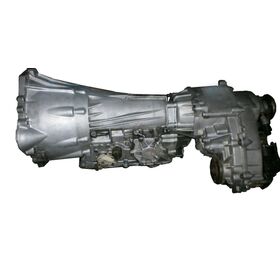
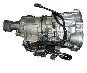
The family of automatic transmissions V4A11 - V4A12 for 4WD (RWD- R4A11) drive of Mitsubishi Pajero Mini was designed by the AT (automatic transmission) department of Mitsubishi in 2000 simultaneously with FWD versions F4A11-F4A12. The difference between V4A11 and V4A12 is in slightly higher transmitted torque, but both versions use the same engine (0.7 liters). The 1-liter engine can be used only for F4A12 or R4A12 (AWD- V4A12). The V4A11 \А12 unit is mainly installed on AWD versions of Pajero Mini for a
Japanese market. These transmissions were aggregated with a minimum
4-cylinder engine (0.7 liters) The design of all sub-modifications
is quite similar, equally reliable, and this transmission goes so long that the cost of the machine
at the time the overhaul of the machine becomes comparable to the cost
of the bulkhead automatic transmission. The gearboxes were adapted for
different engines and different underfoot spaces of the Mitsubishi
mini-cars from (eK WAGON to Pajero Mini).
Number of gearsTransmission TypeDriveTorque (Nm)ATF (full capacity) LATF (change) LATF type4ATFWD/AWD3,52SP III
Technical issues and repair guidelines
The repair of these transmissions mainly consists of replacement of the filter and change of the transmission fluid.In most cases, the reassembly of the transmission, cleaning of the valve body and replacement of solenoids are performed by car owners. In many cases, the replacement of this automatic transmission with the used one turns out to be less expensive than its repair.