
Transmission Diagnostics & Repair
Common Transmission Problems, Diagnostics and Repair Procedures
Technical guides on automatic transmission diagnostics, repair procedures, component testing, failure analysis, and service methods for transmission specialists, rebuilders, parts suppliers, and repair professionals.

Transmission general data
Balancing is used after all components have been replaced and subsequent welding is done. The process of balancing allows transmission service people to find out if there is a bad or uneven weld on the circumference of a Torque Converter. If it is identified, the operator can easily weld on a small amount of material or remove it. Performance transmission and racing transmission specialists pay special attention to Torque Converter balancing.
When you turn the ignition key the Torque Converter starts to rotate together with the engine. Torque Converter of about 250mm in diameter and of about 10 kg in weight imbalance in its RPM can cause such a serious vibration that the entire vehicle will be affected, including fastening elements of the engine and the automatic transmission.
Balancing machine for torque converters allows us to check imbalance of this element with guaranteed accuracy. Precision system implemented in these machines allow transmission repair experts to pinpoint exact place of excessive or insufficient weight.
Transmission general data
The Vacuum Test Unit is used to test the vacuum integrity of all Valve Body hoses and valves. This method of Valve Body testing is considered to be quite a traditional testing solution for transmission shops - it is a money-saver which does a straightforward job. At the same time it doesn’t provide the many advantages of the modern sophisticated transmission service tools. Vacuum tester is often used jointly with a Valve Body test equipment for remarkable results.
The vacuum test allows to evaluate the condition and wear of the valve (plunger) in the body of the hydraulic unit. A worn valve or a hole in the hydraulic unit may result in improper operation, reduced performance or malfunction of the automatic transmission. In most cases, it is possible to assess the wear of the hydraulic unit of the automatic transmission without the vacuum test. However, if you have repaired hydraulic unit with the help of special reamers and valves produced by such manufacturers as Sonnax, a vacuum tester is a must because the vacuum test allows you to quickly and easily test for leaks in the channels of the hydraulic unit.
Transmission general data
In the automatic transmission, the valve body serves as the hydraulic control center responsible for gear shifting and torque converter clutch application. Inside a valve body, one will see a maze of channels, different sets of valves, and a variety of solenoids. These all work together controlled by the transmission control unit or module (TCU or TCM) to direct hydraulic fluid through these passages to the valves activating the required clutch pack or servo to apply or release these elements causing gear changes and torque converter clutch application. Modulation of the components is what provides smooth gear changes over the range of throttle application or driving conditions.
Why is valve body testing important and necessary?
Valve body
testing covers a significant range of tasks. Among these, one may distinguish 5
principal ones as below:
Speed up the process of repair of a worn valve body,Be able to pin-point a source of malfunction within a valve body,Provide confidence in valve body repair for extended warranties,Be compliant with stringent quality requirements,Provide end-of-line testing for a new valve body as a factory product and performance valve body testing.
The only other viable option to test a valve body is to test-in the vehicle, which involves a large amount of labor and technician time especially on newer vehicles where installation and removal of the valve body may require other vehicle components to be removed to gain clearance. Simple remove and reinstallation of a valve body inside a car can take up to 4 hours to complete. If a shop is specializing in transmissions and valve bodies and repair volume is low, this might be an option that works for them, but most shops are competing on price and so the required technician time make s this an expensive option. The real issue with this method is when there is a fault or malfunction that is not obvious and the technician has to perform the install, test, remove, and repair procedure multiple times to try and identify the problem or worn circuit in the valve body. If a shop has any significant volume of transmissions to repair, the technician and owner simply do not have the spare time to do this and needs to avoid time-consuming troubleshooting road tests.
Subsequently, conventional scan tools and pressure gauges do not always suffice to determine what exactly is causing the trouble within your valve body, especially if it has significant mileage. An inexpensive vacuum tester is certainly a must-have for a quick bench test upon tear down. It serves as a cornerstone every time one starts valve body inspection and repair. A vacuum test can identify a worn valve or questionable circuit, but it may be difficult to determine the degree to which a valve, or a bore, is worn and it may not identify the wear as clearly as needed. A valve body tester emulates road conditions and actual hydraulic operation of the valve body in all gear ranges as well as near the normal operating temperature of the valve body. The valve body can be tested at a variety of pressures with temperature control and strict control of solenoid amperage to simulate the hydraulic modulation as gear shifts occur. The performance of the unit under test can then be compared against benchmark data in a graphical or tabular format. This allows a technician to identify faults or questionable data that are not able to be seen in the vehicle. The modern valve body test is a complex and eloquent tool that gives the technician the ability to identify the exact source of trouble, leaving little room for doubt and giving confidence that the repair has been performed correctly.
The ability to provide extended warranties and to keep warranty claims as low as possible have a direct effect on the reputation of a shop. In order to be confident in the repairs to offer these types of warranties it is important that the unit is thoroughly tested using consistent test practices. A shop with high warranty claims, even if addressed and the issues rectified, can suffer from unhappy end customers and this can have a direct effect on the reputation of the shop. Therefore, if one is concerned about delivering the transmission shop’s valve body repair guarantee and protecting the shop’s reputation, quality valve body test equipment is crucial.
Another important factor is compliance with certain requirements for a repaired product. This comes into play if a shop or remanufacturer enters in a contract with larger companies providing multiple repaired or rebuilt units. This is common in fleet accounts where the removal and installation of the transmission is not done by the shop remanufacturing the unit. When doing this kind of work there may be a requirement that repaired or remanufactured units meet a certain quality standard (confirmed by thorough testing).
One more application for advanced valve body testing is end-of-line testing. This is typically larger remanufacturing companies or even OEM that need to make sure that the unit just built is performing as per the specification and there has been no fault during the production process. This can also include performance shops that build valve bodies for racing or for heavy duty / towing applications. The volume may be lower, but the use of a valve body tester is critical in these operations as well.
History and principle of operation of a transmission valve body tester
Valve body test equipment started to become common among transmission repair shops in the early 1990s as valve bodies transitioned from hydraulic cast iron three speed units, to aluminum electronically controlled four speed units. During this pre-digital era the equipment was fully analog with multiple pressure gauges to show readings and even lights with pressure switches to show if there was a minimum amount of pressure in a circuit.Valve body
test equipment has started to gain among transmission repair shops of various
scales back in 1990s and during that pre-digital era the equipment was,
obviously, fully analogous with multiple readings shown on the external gauges.
At that point, the principal components of a valve body tester were the machine itself (mainly a pump and pressure regulation system, the corresponding test plates connecting the test unit to the machine and gauges, and a basic shift controller that would fire the solenoids on or off to achieve each gear). An operator would need to watch the gauges upon a gearshift and make a determination on the quality of the unit based on experience. Nowadays, the data acquisition and processing controller integrated into the testing process plays the key role in modern testing. At that point, the pivotal components of a valve body tester were the machine itself
and the corresponding test plates connecting the test unit with the tested
element. Nowadays, the data acquisition and processing controller integrated into the testing process plays another vital role. Here we may have a close
look at all the three key elements that were specified.
If we break down the key elements for modern valve body test machines, we can see there are three key areas:
1) The principal components of a modern Valve Body testing machine:
The hydraulic pump and motor,Suction and high-pressure filters,Input and output pressure transducers,Heating elements and temperature controllers,Proportional and gate valves,Oil tank (to be filled with automatic transmission fluid),Integrated personal computer or a portable laptop.
Based on this list, the idea is that the system feeds ATF into a valve body under varying pressure and temperature conditions. These would vary to emulate real-life driving conditions.
2) Valve Body and Solenoid test plates
and adapters
These adapters emulate the case connection for a valve body or the bore in a valve body for a solenoid and allow the unit to be connected to the test machine. Connection test plates may have orifices for compatibility with certain valve bodies and plumbing to closely emulate how fluid is fed in the vehicle. Connection hoses and cables differ depending on the model. Typically, plates and cables are model specific and it is one test plate and one cable for a certain model of valve body.
3) The control system to drive solenoids and data acquisition for recording and presenting test data.
With the advent of modern valve bodies coupled with mechatronics units, the task of powering and controlling solenoids is not getting easier or less critical. As there is currently no universal tool to test mechatronics components (link: https://go4trans.com/technical-valve-body-articles/advanced-hydraulics-testing-for-valve-bodies-why-there-is-still-no-universal-solution-for-mechatronics-assemblies/), valve body testers are designed to universally test the hydraulic parts of these valve bodies. With modern units, PWM solenoids require a special approach that is vastly different from ON/OFF solenoid testing and for this purpose more complex controller systems and software are required.
Data acquisition is much more crucial with testing of modern valve bodies. The ability to capture data at 500Hz-1000Hz is necessary to comply with up-to-date valve body testing standards. With 500-1000 reading per second, one can be sure that no data will be missing, and the valve body or solenoid faults will be easy to identify.
The acquired valve body data is then compared against benchmark data previously store in the system. This is done via graphical overlay of the tested performance data. With a visual graphical display pin pointing faults can be done quickly and easily.
What types of valve bodies can be tested?
Modern valve body testing systems are built to be universal and are suitable for transmission repair shops across the globe. The testing process itself does not change from a valve body to valve body. All units are tested hydraulically, and solenoids are checked electrically. The necessary part is that the manufacturer has to be able to provide a valve body test plate suitable for a new / particular valve body.
There are a few aspects of testing for various valve bodies worth touching on separately:
1) Latest model Valve Bodies with mechatronics, or TEHCM testing (for a thorough review, read the article: https://go4trans.com/technical-valve-body-articles/a-good-closer-look-into-mechatronics-units-testing/)
Generally, the mechatronic part is omitted from the testing circuit. There are 2 key reasons for this. Firstly, there is no universal tool that can test all varieties of TEHCM applications. Secondly, a transmission specialist really wants to test all parts separately – to be able to identify the valve body fault most clearly without questioning if it is a valve body or a TECHM programming/fault.
Power Test’s Axiline has a solution to test just a few types of TEHCM applications with their WinDyn Test Cube system. There is number of limitations with this system as the system can only test:
-6HP19, 6HP21, and 6HP26 mechatronics by ZF but not all types of these models (with exclusions by years),
- some GM (General Motors) models: 6L45, 6L50, 6L80, 6L90, 6T40, 6T45, 6T70;
- DQ200 (0AM) and DQ250 (02E) among DSG’s.
Another concern is whether this solution is worth the investment as the Test Cube by Axiline is nearly as costly as the valve body testing machine itself. The standard solution is to use corresponding TEHCM tools by OEM’s – like ZF Testman for ZF.
Other manufacturers of valve body testing equipment have omitted the mechatronic part from their test cycle.
2) Solutions for Valve Bodies popular
in all countries across the globe
Axiline specializes in the USA market and concentrates on the models that drive on the North American roads: GM, FORD, Chrysler, and Allison. For example, the Axiline solution line for GM is widely used globally on popular models such as 4T65-E, 5L40E, and 6T40/45. Some of the supported models are most common in the US becoming quite old – for example, 200C, 400. Concentration on the USA models is not surprising as the USA car market is the largest world market – however, this leaves transmission repair specialists from other countries of the world not covered.
Raytech or Transpeed, which are China-based, offer solutions based upon models popular on the Chinese roads - although they trade globally and strive to provide solutions across the globe.
Hydra-Test has opted for universality and the solution that covers all of most popular models globally and locally: German valve bodies by ZF and VW; American valve body models by Ford, GM, and Chrysler; Asian transmission valve body models by Hyundai, Kia, Toyota, Nissan, and more.
Kinergo’s Valve Body test machine, an emerging solution from the advanced post-Soviet industrial region, is covering what is in demand and the team provides solutions inspired by other manufacturers.
3) Continually adding new testing adapters and solutions
As a repair technician needing to stay current with the ever changing automatic transmission repair market one would want to invest in a tool that will be on pace with the trends, model updates, and new models of the industry. Therefore, it is vital that the likes of the 9HP by ZF, AC-60E by Toyota, 8 speeds by GM, the 10L by Allison, or latest CVT’s like JF016 are being added to the range of solutions by your supplier of automatic transmission repair equipment.
4) Custom-built solutions
If you are developing your own valve bodies or if you are producing performance valve bodies, it is necessary that the manufacturer of your equipment knows to handle solutions that are demanded by your company. A need for personalized valve body testing can be met with reluctance to take it on or a high cheque. However, for some manufacturers this is a good cause for faster introduction of newly-launched valve body models to their product range. For instance, this is how Hydra-Test took on heavy duty solutions: although the company specializes in the models for light-duty civil vehicles, they have introduced VOLVO CE (Construction Equipment) PT2116-PT2509 and PT1860-PT1861 as there was a demand for this.
How do valve body testers check individual solenoids?
Generally, valve body testing equipment allows for solid verification of solenoid operation. The technician can see how solenoids installed in a valve body perform in the valve body assembly. Here we shall focus on how valve body testers can be used with solenoids separately from the valve body.
If a transmission repair specialist is just beginning to repair and remanufacture their own valve bodies, they may opt for a solenoid tester and valve vacuum tester combination. A vacuum tester is conventional inexpensive tools – Sonnax vacuum tester is the option of preference.
There are several methods of solenoid testing but a most thorough check is with implementation of advanced solenoid testing equipment (check the solenoid testing equipment section). The question comes up on if a transmission technician has to have separate solenoid tester and valve body testing machines? The answer really depends upon the volume or work a shop has. If you can split the time needed to test solenoid and valve bodies on one machine then there are solutions to test both in a valve body tester. However, if the volume becomes such that testing solenoids holds up being able to test valve bodies, then the shop is really in a position of needing two separate machines.
The option of testing solenoids with the valve body testing equipment makes sense when you have lower volumes of work. This feature is easy to add as by default the hardware, software and the controller of a valve body testers is more advanced than that of solenoid testers. They only step needed is addition of solenoid testing blocks with a valve body tester so inquire if your potential supplier has the ability to easily add this feature to the valve body test machine.
Here is an example of the UK’s Hydra-Test add on adapter package for solenoid testing on their VBT Deluxe. A solenoid adapter plate is placed in place of a typical valve body pate and their line of solenoid test blocks fit exactly as they do in the solenoid machine. The solenoids can now be checked hydraulically and electronically with all the same quality of data capture and processing as the valve body testing.
Importance of hardware with transmission valve body test stands
Hardware plays crucial role in reliability of the testing equipment and certainly contributes to having the equipment up to actual standards as time advances. The are many internal components that serve to capture and process transmission valve body operational data. These are the pressure transducers, power supply, transducer distribution board, cabling kit and leads, temperature controller, and so on.
The hardware serves as the control center of a valve body test system and it is the key of valve body performance data processing by using pulse width modulated solenoid outputs, analog inputs, discrete inputs, frequency inputs, analog outputs, temperature sensors – as key data acquisition components.
Most often, suppliers of testing equipment develop and apply their own hardware unless there is a need for some specific solution. An example of past cooperation between companies in the industry was Mustang Dynamometer and PCS (Powertrain Control Solutions). PCS controllers were private labeled for Mustang as a means to support a large variety of transmissions in the mid-2000’s for their tests at the time. However, cooperation between a few parties in not a strategy to last long enough and the best approach is using own solutions.
Hydra-Test has brought the controller development in house with their initial release of their HTC-K controller and more recently the HTC-S controller. This is the latest controller capable of valve body and transmission testing. The hardware components here are built to last with extra protection and convenient modular system, so the system can grow as a customer needs more capability and/or as new units are added and need to be tested.
How to repair this transmission (Videos)Answermatic Valve Body Test machineKinergo Valve Body Testing machineHydra-Test Valve Body test machine guideHydra-Test Valve Body test machine overviewHydra-Test 0AM (DQ200) valve body testing on a benchZF 6HP19 - valve body testing on Chinese machineValve body testing explained A6MF valve body testing on Chinese testerVacuum testing with Sonnax toolsATS Diesel Valve Body testing on a bench
Instruction manuals and useful linksLink typeSourceDescriptionwebBuy Hydra-Test Valve Body tester
Transmission general data
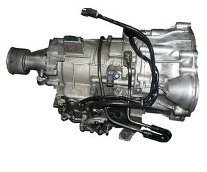
The family of automatic transmissions V4A11 - V4A12 for 4WD (RWD- R4A11) drive of Mitsubishi Pajero Mini was designed by the AT (automatic transmission) department of Mitsubishi in 2000 simultaneously with FWD versions F4A11-F4A12. The difference between V4A11 and V4A12 is in slightly higher transmitted torque, but both versions use the same engine (0.7 liters). The 1-liter engine can be used only for F4A12 or R4A12 (AWD- V4A12). The V4A11 \А12 unit is mainly installed on AWD versions of Pajero Mini for a
Japanese market. These transmissions were aggregated with a minimum
4-cylinder engine (0.7 liters) The design of all sub-modifications
is quite similar, equally reliable, and this transmission goes so long that the cost of the machine
at the time the overhaul of the machine becomes comparable to the cost
of the bulkhead automatic transmission. The gearboxes were adapted for
different engines and different underfoot spaces of the Mitsubishi
mini-cars from (eK WAGON to Pajero Mini).
Number of gearsTransmission TypeDriveTorque (Nm)ATF (full capacity) LATF (change) LATF type4ATFWD/AWD3,52SP III
Technical issues and repair guidelines
The repair of these transmissions mainly consists of replacement of the filter and change of the transmission fluid.In most cases, the reassembly of the transmission, cleaning of the valve body and replacement of solenoids are performed by car owners. In many cases, the replacement of this automatic transmission with the used one turns out to be less expensive than its repair.
Transmission general data
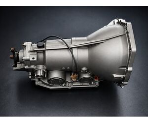
Flashomatic
automatic gearbox was also named as BW8 (1956-66)/BW12 (1956-71). This gearbox had
been actively installed on different models of Packard, Rambler, Studebaker
during 1956-71.
Number of gearsTransmission TypeDriveTorque (Nm)ATF (full capacity) LATF (change) LATF type3ATRWD9,84,2ATF Type F
This transmission is considered to be quite durable due to its iron case. The BW-12 was installed on some Ford vehicles in 1973-74.It is a hydraulically controlled RWD gearbox. This gearbox resembles Ford-O-Matic manufactured in 3 different case sizes used from 1951 until 1968) and FMX gearbox (released in 1968), but few of the parts are interchangeable.
Transmission general data
The
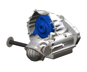
THM425 (and later 325) is a 3-speed automatic gearbox designed and released by
GM. The structure of the THM425 is based on the THM400; most spare parts in
these gearboxes are directly interchangeable and some others can be adjusted
with the help of slight modifications. The THM425 was designed for Oldsmobile
Toronado and Cadillac Eldorado.
Number of gearsTransmission TypeDriveTorque (Nm)ATF (full capacity) LATF (change) LATF type3ATRWD12,36Dexron II
More lightweight gearbox THM325 took the
place of the THM425 in both car ranges in late 1978. Since 1979 and later longitudinal
engine FWD cars have been equipped with the THM325. The THM325 was upgraded to
THM325-4L with an overdrive added in 1982, but all cars with this gearbox
switched to more-common transverse engine mounting in 1986.
How to repair this transmission (Videos)TH-400 rebuild part 1TH425 Governor Gear RemovalTH400 Rebuild: Governor
Transmission general data
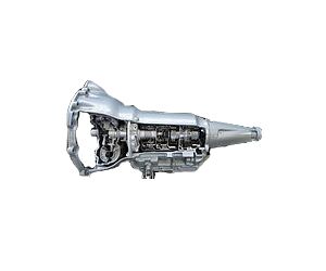
The automatic gearbox THM250 is based on the
THM350. This gearbox was released in 1974 and was applied in Chevrolet cars.
The THM250 was developed and designed by GM as a part of Turbo Hydra-Matic family
of automatic gearboxes. When taking into consideration the internal structure
of the gearbox, the THM250 is very similar to THM350, apart from the
intermediate clutch package with a band adjuster.
Number of gearsTransmission TypeDriveTorque (Nm)ATF (full capacity) LATF (change) LATF type3ATRWD9,55,6Dexron II
Generally, the THM250 was attached to small displacement engines. In 1976 this gearbox was taken out of production and was replaced by the light-duty THM200 transmission. However, the THM250 reemerged in 1979 as the THM250-C as a result of numerous issues withTHM200/200C. The 250C version had a reduced weight thanks to the use of a central gear shell applied the THM350, but with three holes to decrease flywheel mass and the low/reverse piston with eight notches.
Instruction manuals and useful linksLink typeSourceDescriptionpdfoldcarmanualproject.comRepair manual THM250
Transmission general data
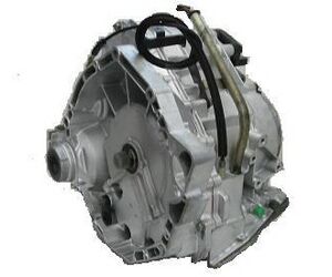
CVT VT1-27T Mini (or general name for this family - VT1F) found application on Mini BMW. In addition to Mini, this CVT was offered to Volvo, Land Rover, Hyundai, but this transmission rarely comes to repair services and its hard to find spare parts for repair of this CVT. The following modification CVT VT2 was a budget-friendly solution. This CVT had been offered to many automakers from 2009 to 2013.
Number of gearsTransmission TypeDriveTorque (Nm)ATF (full capacity) LATF (change) LATF type∞CVTFWD1507,64,3Esso EZL799
Technical issues and repair guidelines
This CVT has a typical design (with a solid reserve on transmission components) with a push belt and does not require repair for many years, except replacement of ATF and filter, and later – replacement of Bosh belt. This CVT was developed specially for BMW mini.
Settings of the VT1 control unit are adjusted for preserving expensive cones at low speeds, when the belt and surfaces of cones operate closely to the limit. Cones have wear-resistant cover of operating surfaces with the use of space technologies can not be rebuilt and not supplied to the repair market. CVTs of this generation are very sensitive to the level of ATF, therefore the check of this parameter is very technology-savvy.
Rare overhauls with reassembly of spare parts, wear-out of which leads to pressure losses on friction elements and as a consequence their (frictions) wear-out require the repair kit of gaskets and seals. While maintaining these CVTs experienced specialists replace the filter and change ATF as often as possible to avoid time consuming search operations for spare parts. Simultaneously with change of fluid and filter replacement, it is recommended to check the belt for wear-out of the protector. If there are any suspicions about wear-out, it is better to replace the belt. Even slightly wornout belt increases the risk of slipping (metal-on-metal) in situations with usual "non-sporting" acceleration in order to outrun the truck ahead. Generally, this CVT is quite comfortable and “invincible” under the condition of proper care. It is one of the top CVTs on the market.
How to repair this transmission (Videos)Replacing Belt part 1Belt replacement pt2Mini Cooper CVT overviewZF VT1 CVT Transmission Stepper MotorRover - Service Insight - VT-1 Automatic TransmissionMini CVT transmission teardownMini CVT teardown test clipMini Cooper cvt adaptation
Transmission general data
The
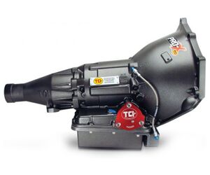
Powerglide is a two-speed automatic gearbox constructed by GM. This gearbox was
mainly installed on Chevrolet vehicles (1950-1973) and on some Pontiac cars. The
gearbox was uncomplicated and extremely reliable, that gained trust of
customers. In spite of its old-fashioned construction Powerglide is still
popular in drag racing (as well as in mud racing) because it is not complicated
and robust.
Technical issues and repair guidelines
The Powerglide is a two-speed automatic gearbox constructed by GM. This gearbox was mainly installed on Chevrolet vehicles (1950-1973) and on some Pontiac cars. The gearbox was uncomplicated and extremely reliable, that gained trust of customers. In spite of its old-fashioned construction Powerglide is still popular in drag racing (as well as in mud racing) because it is not complicated and robust.
How to repair this transmission (Videos)Powerglide Transmission CutawayLEARN TO REBUILD THE POWERGLIDE
Instruction manuals and useful linksLink typeSourceDescriptionwebSonnaxUnderstanding & Overcoming the Powerglide Servo Pin Bias Effect
Transmission general data
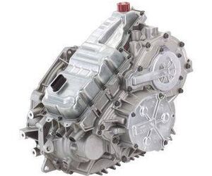
The CVT transmission VT20E was used for FWD Opel Vectra of English and German assembly with engine capacity equal to 1.8 liters. The VT25E modification found application in American FWD Saturn VUE and Ion (2.2 liters capacity).
This CVT equipped with a push belt is perfectly adjusted, therefore it rarely gets in repair services. During the first 150-200 thousand kilometers of exploitation, drivers just should not forget to replace filters and change transmission fluid in a timely manner (depending on the driving style).
Number of gearsTransmission TypeDriveTorque (Nm)ATF (full capacity) LATF (change) LATF type∞CVTFWD1756,5VTF DEXRON CVT
Technical issues and repair guidelines
A minimum set of procedures during the overhaul of these CVTs includes the following:
- Belt replacement
- Replacement of all spare parts, gaskets, seals, sealing strips, rings, which often include two pistons
Friction elements of Forward pack often get burnt, including a bearing disc and pistons, the whole set of frictions gets replaced.
Problems of “old” VT25E:
- Valve Body, VT25E CVT.
- Planetary gear, Reverse (6 Gear) .
It is required to replace CVT when cones get worn out (because of aggressive accelerations "at a cold motor" and driving with contaminated oil).
Which cars run with this gearbox?BrandModelYearTypeEngineOpel / VauxhallVECTRA02-04CVT FWDL4 1.8L
How to repair this transmission (Videos)Repair cvt VT25-E/VT20-E, Saturn, Opel
Instruction manuals and useful linksLink typeSourceDescriptionpdfwww.at-manuals.comScheme VT20Epdfwww.at-manuals.comScheme VT25E
Transmission general data
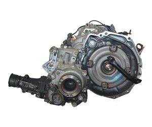
The infinitely variable speed transmission RE0F21A (JF012E) was developed by Jatco in 1999 on the basis of RE0F06A as a CVT solution of the “extra-lite” class with a minimum torque. For several years, this CVT had been installed on Nissan Cube with the engine capacity equal to 1300 cm3. It was also tested on Italian Fiat (DLTC46FHJ1AA) as an automatic alternative for Punto, Albea, Uno and others, which were in production until recent years. In terms of design, this CVT is similar to RE0F10A, JF011E, RE0F06A.
Number of gearsTransmission TypeDriveTorque (Nm)ATF (full capacity) LATF (change) LATF type∞CVTFWD13052,5CVT Fluid NS-1
Technical issues and repair guidelines
Repair procedures for this transmission usually involve timely fluid change and sometimes filter replacement. Sometimes it comes to replacement of the belt which fits to some related CVTs from Honda and Mitsubishi. In rare cases, burnt Forward and Reverse frictions get replaced. Frictions get burnt because of worn-out rings and gaskets (Repair kit of gaskets and seals). Burnt fluid damages rubber seals, therefore experts recommend to replace all rings of this CVT RE0F21A in the course of overhaul. The major part of spare parts for repair of this CVT is bought on the market of used spare parts, and repair of this CVT is less frequent than replacement for "used" CVTs.
Which cars run with this gearbox?BrandModelYearTypeEngineNissan/DatsunCUBE00-02CVT F/4WDL4 1.3L
Instruction manuals and useful linksLink typeSourceDescriptionpdfautomaticchoice.comScheme RE0F21A
Transmission general data
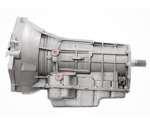
The 6-speed automatic transmission 68RFE produced by Chrysler has been installed since 2006 on pickups Dodge RAM 2500-3500 with engine capacity of 6 liters and higher. In terms of design, this transmission is based on 45RFE and on the 5-speed 5-45RFE.
Number of gearsTransmission TypeDriveTorque (Nm)ATF (full capacity) LATF (change) LATF type6ATAWD15,76,5Mopar ATF+4
Technical issues and repair guidelines
During the reassembly, specialists use the following repair kits:
-Kit of gaskets and seals or a complete kit of gaskets, seals, frictions and steel discs (Master Kit)
- Kit of pistons (5 pieces). Many details and spare parts are common with the 5-45RFE.
- The complete kit of friction components is ordered for the automatic transmission reassembly.
The valve body and the block of solenoids are the main vulnerabilities for the 5-45RFE transmission. After 100 thousand kilometers, it is required to monitor the state of these components (oil pressure, cleaning). The valve body and solenoids often reach the end of their service lifespan after 3-5 years of active exploitation, especially with the worn torque converter clutch.
There are problems with the 68RFE torque converter (overrunning clutch, friction, gaskets). It is recommended to replace spare parts in the torque converter quite early, because of problems related to American torque converters.
Which cars run with this gearbox?BrandModelYearTypeEngineDodgePICKUP/RAM 2500-350009-166 SP R/4WDL6 6.7L
How to repair this transmission (Videos)Input Drum AssemblyOD clearance checkDRUM STACK-UPTeardown Inspection
Instruction manuals and useful linksLink typeSourceDescriptionpdfwww.at-manuals.comIntroduction to the 68RFEpdfwww.at-manuals.comScheme 68RFEpdfSonnaxValve Body Layout 68rfepdfSonnaxVacuum test 45RFE, 545RFE, 65RFE, 66RFE, 68RFEwebSonnaxSolving the 6R80 Transmission Leak Mystery